BUILDING A CYCLEKART

BUILD SERIES no. 2: Rear axle and drive
In the “classic formula” the drive system is a Comet Torq-a-verter (a variable belt transmission) running a 10 tooth drive sprocket by way of a #41 chain to a 60 tooth driven sprocket on a rigidly mounted axle with one wheel drive.
Solutions on our cars range from the Austro-Daimler at one extreme with its full-on differential axle and quarter elliptically sprung engine sub-frame, to the Miller and Fiat with their dirt simple, rigidly mounted live axles. All our schemes work well. The exotic ones don’t really offer huge benefits over the simplest solutions.
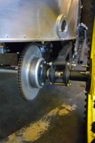
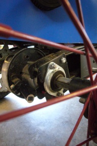
Let’s start with the Panhard. This car uses the classic scheme. A GTC clone of the Comet drive is mounted to the engine vertically with the driven pulley set at the bottom. A 10 tooth, #41 sprocket drives a 60 tooth driven sprocket on the axle. The motor is mounted just in front of the rear axle. We call this position the “mid-engine” scheme. Putting the engine in this position pushes the driver forward and balances the chassis nicely. It also usually makes the rear bodywork easier. The Panhard generally runs with one-wheel drive. This car has a long wheel base and wide track. One wheel drive allows the car to steer more easily. The Panhard would have massive understeer with a live axle. The axle can be locked up on both sides if desired though, to run a hillclimb for example. On this car, the AZ 1861A axle bearings are mounted to the frame rails. (this part number is a kit number: bearing + flangettes + hardware) The frame rails are drilled with a hole saw to allow the axle passage with a large enough hole on the bearing side to allow the bearing flangettes to sit flat on the rails.


The Miller and the Fiat are similar, but AZ 8127 axle hanger weldments have been welded to the frames instead of the axle being run through the frame rails. The Miller has 1’ x 2” frame rails so running the axle through them is not an option. The weldments face down - the axle is under the frame. The are two more axle hangers on the engine mount. The axle supports the engine. The Fiat has 1’ x 3” rails but these drop below the axle and the weldment is on top of the rails. The Fiat motor position is similar to the Panhard. The Miller motor (the only Briggs motor in our group) is mounted above the rear axle. The Miller uses a Comet drive. It is angled back and down. New mounting holes had to be added and some grinding done to the transmission unit to make this work. A 12 tooth #35 sprocket drives a 72 tooth #35 sprocket on the rear axle. The Miller scheme is incredibly dense but somehow it all fits. The first generation Miller had a go-kart type centrifugal clutch, or rather a series of them because they kept failing. When one of these burnt up clutches blew into a hundred pieces and a couple chunks almost went through the plywood seat back, the car was converted to variable drive. Go-kart type clutches work for a while on pavement but the leverage of the 17” wheels and the rough conditions on dirt defeat them in short order.


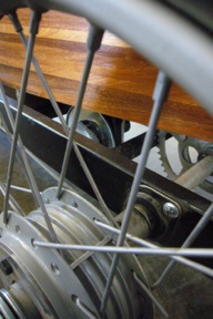
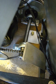
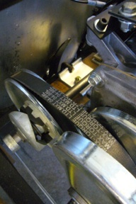
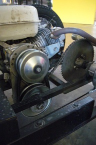
The GN also tried a go-kart clutch in an early (failed) scheme. The GN now has a Max-Torque transmission. This drive is a little different from the Comet type. Where the Comet type uses an asymmetric belt and the pulleys are fixed, expanding and contracting in one direction, the Max-Torque unit has a symmetric belt and the driven floats on a jack-shaft. The advantages of this unit are that is has a lower overall ratio than the Comet (the car accelerates quicker with more snap). The disadvantage is the complexity of the required jack shaft. A 12 tooth #35 drive sprocket is fitted to the opposite end of the jack shaft (from the transmission driven) and pulls a 72 tooth #35 sprocket on the axle. This sprocket doubled as a band brake drum on an earlier (failed) brake scheme. The jack shaft and the axle are mounted to a subframe via pillow block bearings. The subframe, or motor block, is laminated 1 1/2” thick cabinet plywood. The thick plywood mounting is something this builder (now) believes fervently in. The dampening effect of the wood blunts the vicious vibration of our one cylinder engines and is most welcome. The jack shaft is mounted on top of the block at the front and the axle on the bottom at the rear. The engine sits over the live axle (slightly forward). Everything is on trailing 1/4 elliptic springs. Kids, don’t try this at home! Everything moves every which way and taming this beast has taken a lot of fiddling. It all works now and, in theory, provides the best traction of all our cars but there are “interesting” handling trade-offs. If you have read in the vintage press about the quirky handling of GN’s and early Frazer Nash’s at speed, you can drive this car sometime and experience the same, quite startling, corner hopping. The reason for all this kookiness of course was to get the right LOOK at the back and to achieve the extreme rear seating position of the inspiration car. A lot of hassle for what!? The 1/4 elliptic springs are 36” buggy springs cut in half. The axle bearings are carried in flangettes attached directly to the springs. AZ 1849 “deluxe” tie rods are utilized as the lower trailing links. Honestly, unless you are obsessed with nutty challenges, stick to the simple, very functional, schemes outlined above.


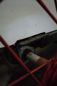
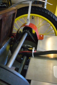
The Peugeot scheme also sports quarter elliptic rear suspension but is more sane than the GN. On the Peugeot, the engine is rigidly mounted to the chassis in the “mid-engine” position, the simple Comet drive unit is vertical again and a 10 tooth driver pulls a 60 tooth sprocket on the axle. The trick with the Peugeot rear suspension is that it is severely restricted. It moves but only a little. A #40 chain is used. This chain runs on the same sprockets as a #41 but is wider (and stronger). The extra width is just enough to handle the slight inclination changes of the live axle relative to the drive. This scheme performs beautifully and looks good, matching the inspiration car but it is complex. As on the GN, the axle bearings are carried in flangettes attached to the springs but on this car AZ 8127 weldments (not welded) back-up the flangettes. A fabricated strap ties the bottom to the chassis. There are four bearings on the axle.
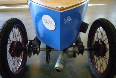

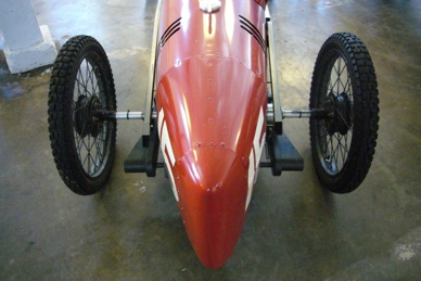
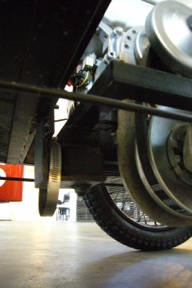
Bloody Mary is an entirely different approach. The inspiration car is about as ill-suited to making into a rear engined cyclekart as could be picked. All engine and hood with the driver sitting just in front of the rear axle, almost nothing behind him - nowhere to hide the engine! An extreme engine placement behind and below the rear axle was necessary. The transmission is made from Comet parts but not the all-in-one Torq-a-verter unit. The drive pulley is mounted on the engine and the (long) belt runs up to the driven pulley mounted on a 3/4” jack shaft above and forward of the engine. A 12 tooth #35 drive sprocket on the other end of the jack shaft drags a 72 tooth driven sprocket in extreme proximity directly below. As on the GN, the axle and jack shaft run in pillow block bearings. The pillow blocks are above and below each other on opposite sides of the frame rails. Using pillow blocks is critical in this scheme because the belt tension and chain tension are both adjusted by shim plates and sliding the blocks on their oval holes. This car usually runs with one wheel drive but like the Panhard, it can be locked up when desired.


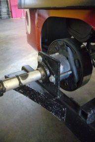
The KING of drive complexity is the Austro-Daimler. It is also the king of rear end failure. Huge prowess when running but also a frequent track side decoration.This car has a real differential. The unit came from Northern Tool and is a simple Peerless unit. The differential axle is mounted rigidly on a sub frame with the engine. The outer ends of the axle have a second set of bearings connected to inverted 1/4 elliptic springs. These springs suspend the rear axle and engine sub-frame. The front of the engine sub-frame is attached to the chassis with a modified, scrap bin, Volvo transmission mount. This is a robust late generation solution after several earlier joints failed. This spindly differential is not intended for our race conditions and has had issues with bearings and shafts walking but when it is all working it offers a tremendous drive. Rear end cornering on this car is unrivaled by our other schemes. The engine on the Austro-Daimler is farther forward than any of our other cars and that helps the balance immensely. The odd Porsche designed inspiration car lets all this happen and still look more or less correct as a cyclekart.

Axles, bearings, jack shafts, sprockets, chain, etc., are all available as Azusa parts.
Comet went out of business a year and a half ago but GTC makes a clone of the Torq-a-verter which suits our purposes perfectly.
A chronology will give some clues to the development of our thinking:
-
1.Peugeot - scheme unchanged. “Mid-engine”, Comet. 1/4 elliptic live axle.
-
2.Miller - axle consistent but drive unit changed from go-kart clutch to clutch with reduction gear to present Comet type. Engine over axle, rigid live axle.
-
3.GN - first scheme had a go-kart clutch and insane double chain drive set-up with changeable ratios (changeable, not shiftable) working with a rigidly mounted axle. This failed in such a twisted mess that the back of the chassis had to be cut-off, hence the entirely new second rear-end. Engine over axle, Max Torque drive, jack shaft, 1/4 elliptic live axle.
-
4.Austro-Daimler - scheme is more or less as originally intended but has evolved immensely in detail (strengthened). “mid-engine” (the most forward), Comet, 1/4 elliptic differential axle.
-
5.Fiat - scheme unchanged. “Mid-engine” (low), Comet, rigid live axle.
-
6.Panhard - scheme unchanged. “Mid-engine”, GTC Comet clone, rigid one wheel drive axle.
-
7.Bloody Mary - scheme unchanged. Rear engine (extremely low) behind axle, Comet, jack shaft, rigid one wheel drive axle.
Wednesday, January 19, 2011

